Following several years of design studies of UV imaging interferometers (mainly for Solar Physics Missions), we can now propose a very complete and mature mission concept with comprehensive mechanical and optical realization schemes and image reconstruction scenario. Furthermore, the major issue, the validity of the use of interferometric techniques (recombination principles, cophasing possibilities) was demonstrated both on a laboratory representative breadboard and directly on the Sun - the feasibility and performances of the cophasing of two telescopes on extended objects. These results really open the possibility to use and discover from solar interferometers in Space. With a 1 meter baseline or so, a UV imaging interferometer will reach a spatial resolution of 0.02" and a field-of-view of 40" allowing to untangle the confining and dissipating mechanisms and processes in the transition zone and corona (spatial resolutions are a factor 40 higher than any previous experiments in Space). Of further advantage is that this "small" interferometer will provide the first complete test of interferometric technologies in Space before investing in - much - larger Astrophysics or Earth Observation missions in the future.
Back in 1989 we proposed the Solar Ultraviolet Network
(SUN) a 4-telescopes interferometer for imaging (by rotation of the
array as a whole) the fine structure of the Sun (Damé et
al., 1989). This instrument and the Mission it belonged to,
SIMURIS (Solar Interferometric Mission for Ultrahigh Resolution
Imaging and Spectroscopy ), eventually completed a First Phase of
Study in the context of the Space Station in 1991 (Coradini et
al., 1991). Studies were pursued up to 1993 when a smaller
version of the interferometer, MUST (Multi-mirror Ultraviolet
Solar Telescope) was considered for the External Viewing Platform
of the Space Station. In parallel, the MUST interferometric concept
(5 telescopes on a circular baseline: snapshot imaging) was also
proposed for a satellite mission (Damé et al., 1993a)
with some success. MUST, which new acronym is SOLAR NET, is now
considered both for the next ESA Medium Size Mission (M4) and for an
Express Pallet Adapter on the Space Station (this last version with
accent on the demonstration of interferometric technologies).
In support to ESA studies, CNES engaged in 92 Research and
Technologies (R & T) funds for the realization of a
two-telescopes breadboard to demonstrate the heart of the system: the
measurement of an absolute phase and the cophasing control of the
interferometer.
The breadboard was completed in spring 1994 and by September 1994
a complete laboratory demonstration of the cophasing of
two-telescopes on extended objects was achieved with remarkable
performances. During summer 1995 the breadboard was installed at
Meudon Observatory at the “Grand Sidérostat de
Foucault” and the first direct cophasing on the Sun was made
with a phase control of l/140. These
cophasing experiments were repeated in 1996 and better performances
were achieved (l/240). Following these
successes we can now sustain that we have the recipe and the cooking
skills for the realization of a major instrument for the advance of
Solar Physics at the beginning of next century: the Solar
Interferometer, either on ground (MACS: Multi-Aperture Cophased
System) or in Space (SOLAR NET).
In the following, we briefly recall the objectives and concepts of the Solar Interferometer (SOLAR NET), explain the constraints imposed by the measurement of a phase over extended objects and present the laboratory and sky results obtained with the first solar interferometric experiment of cophasing on extended objects (Sun and Planets). We conclude on the required resources and descriptions of different versions of SOLAR NET either suited for Space Station (Early Flight Opportunities) or satellites, ESA Medium Size Mission M4 or CNES/AEROSPATIALE new platform PROTEUS.
The relevant minimum observable scale in the solar atmosphere may
be of the order of 10-30 km since smaller scales will probably be
smeared out by plasma micro-instabilities (such as drift waves). This
scale range is comparable to the photon mean free path in the
chromosphere. Slightly larger scales can be expected in the corona
(though gradient across coronal loops may also be a few km).
Altogether this situation is rather fortunate because we have access
to higher resolutions in the far UV than in the visible and X-rays
(multilayer telescopes are limited to resolutions of 1 arcsec or so).
In the UV, the emission lines are generally thin, i.e. not affected
by the optically thick transfer conditions which prevail in the
visible and near UV lines accessible from ground, and we can expect
to see structures with scales 10 to 30 km. In the visible, thick
transfer in the atmosphere blurs the signature of structures and
nothing smaller than 70-100 km should be observed. This means that
with a single instrument of meter class diameter we have the
appropriate, scientifically justified, spatial resolution for
both the UV (20 km at Lyman Alpha 121.6 nm) and the visible / near UV
(60 km in the Ca II K line 396.3 nm).
A breakthrough in high spatial resolution observations (20 km is 40 times more spatial resolution than any previous solar instrument in Space) should allow to understand in finer physical details processes like magnetic heating in coronal loops (temperature profiles, time dependence, spatial localization of heating processes) but, also, by access to visible wavelengths, the coupling between turbulent convective eddies and magnetic fields in the photosphere. Another scientific objective is the plasma heating processes and thermal inputs of flares and microflares and their fine magnetic field structures. More details on the scientific objectives can be found Damé et al. (1993b).
If the need for high spatial and spectral resolutions is commonly
agreed, the question left is why an interferometer and not a
single-dish large telescope. The answer is that the required
measurement needs exceed conventional instrumentation limitations. A
1 m telescope diffraction-limited in the far UV is, in practice,
exceedingly difficult to construct. And, even assuming that such a
perfect 1 m telescope could be built for the far UV, it would be more
costly and difficult to control and assemble than an
interferometer.
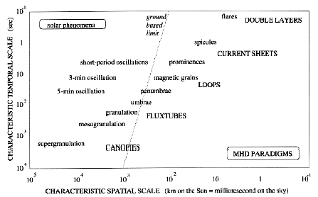
Figure 1. Solar physics requirements: space-time characteristics of solar phenomena (small print) and paradigms of magnetohydrodynamics (capitals). The axes specify intrinsic scales, corresponding to desirable resolution. The dotted line is the ground-based optical resolution limit, including new techniques (adaptive optics). This figure portrays the main reasons why solar physics needs interferometers in Space. Of course, there are other types of resolution not plotted here, such as spectral resolution or polarimetric resolution. These define secondary instrumentation and observation modes. Altogether, this figure displays quite fortunate circumstances. The magnetic structuring of the outer solar atmosphere presents a rich array of astrophysical conditions for us to inspect and learn from. They are faithfully encoded in short-wavelength diagnostics of which the line formation is optically thin. The proximity of the Sun translates into shortness of the required baselines compared to non-solar astrophysics. A meter suffice for all phenomena because the smallest (e.g. flare kernels) are also best observed at the shortest wavelengths. Thus, Space observation with relatively modest baselines suffices for solar physics.
The Michelson interferometric approach represents significant
advantages over diffraction-limited large telescope imaging. Only
small telescopes are necessary and their small secondary mirrors can
act directly as active pointing mirrors, without requiring
intermediate optics for this purpose. Telescopes larger than 40 cm
cannot be polished to the specification of l/8 at Lyman a (121.6
nm) while small ones can. The Hubble Space Telescope, a 2.4 m mirror,
even with a perfect figure, would still be a factor 10 away (0.1
arcsec rather than 0.01 arcsec) from its diffraction limit in the far
UV due to the residual ripples left on its surface by the polishing
process. Interferometry requires to control the residual optical path
delays between telescopes but this, consequently, guarantees a
perfect output wavefront suitable for diffraction-limited imaging.
Adaptive optics is not an alternative to obtain the correct figure
precision of large mirrors or to control the resulting errors,
because of thermal cycling in orbit. Note that aligning a segmented
mirror requires 6 degree of freedom and a control of the distance
between the primary and secondary mirrors. This very complex control
loop is not required with an interferometer made of small telescopes
(beside fine pointing needs, only one degree of freedom is required:
the phase control).
Altogether, the modest baseline required to obtain major scientific results and the simplified control of an imaging interferometer (which doesn't need an absolute metrology like astrometric programs) result in very reasonable cost and mass which open solar (and planetary) interferometry programs to the medium size satellites programs and to the limited accommodation capabilities of the International Space Station. SOLAR NET, completed with XUV telescopes and larger field instruments, is the baseline of the Reduced SIMURIS Payload adapted to small platforms and satellites (cf. Table 1). XUV spectrometers and solar irradiance monitoring instruments could also be envisaged for completeness as a solar observatory. For the Space Station, a simplified version of SOLAR NET (3-telescopes) is envisaged with both scientific and technical objectives (demonstration of a complete interferometric system in Space).
To study the ultimate fine structure of the Sun, a solar
interferometer needs to image an extended field-of-view (FOV) covered
with complex structures. And, since many structures of interest are
evolving rapidly (in a few seconds or even less), this imaging cannot
be achieved by classical long-baseline interferometry techniques
where fringes' visibilities are measured sequentially.
These constraints (FOV and time resolution) prompt to design an
interferometer with instantaneous imaging capability i.e., first, to
the choice of a compact array. By compact is meant that the spatial
frequency coverage of the array is comparable to a single dish
telescope in one fundamental aspect: complete coverage of spatial
frequencies, i.e. there are no zeroes in the modulation transfer
function of the array. Image restoration is, in this case, based on a
direct deconvolution. A central issue for interferometric imaging is,
therefore, a proper (i.e. compact) configuration of the array.
Table 1. Model Payload of the Reduced SIMURIS Mission (M4 and PROTEUS proposals).
|
|
|
|
|
|
|
|
|
|
|
0.025" / 0.002 0.10" / ~ 20 0.06" / 0.001 |
|
Five Ø25 cm Gregory telescopes on a baseline of Ø90 cm followed by two double monochromators in cascade |
|
|
|
Fe XX/XXIII 13.3 Fe IX/X 17.3 Fe XII/XXI 19.2 Fe XIV 21.1 |
|
|
Ø10 cm Ritchey-Chrétien telescope with selectable multilayers |
|
|
|
Lyman a 121.6 C IV 155.0 Continuum 160.0 He II 30.4 |
0.6" / ~ 10 0.6" / ~ 0.8 " 3" / ~ 1.5 |
|
Ø10 cm Gregory
telescope with filter wheel (including a FP filter ) Ø10 cm Ritchey-Chrétien telescope (multilayers) |
The other important requirement is to control the residual optical
path delays between the different telescopes to a fraction of a
wavelength, i.e. to cophase the interferometer. This allows
all the recorded fringes to be used instantaneously, since not
affected by a significant phase problem (thus allowing a robust image
reconstruction approach). The consequence of importance brought by
this cophased approach is that, permanently, we have the insurance of
a near perfect wavefront (stable transfer function), the telescopes
of the array being controlled to their optimum phase position.
This complete spatial frequencies coverage is the basic difference
between classical two-telescope interferometers and compact
multi-telescopes interferometers. In the two-telescopes case, the
fringes do contain high resolution information even though most of
the spatial frequencies are lacking between the low frequencies - due
to the area of the small telescopes' primaries - and a high
resolution peak due to the pair of telescopes. The data analysis then
relies, first, on a measurement of the fringes' visibilities at these
specific spatial frequencies, second, on a sampling of the other
spatial frequencies (e.g. by moving the telescopes) and, third, on an
image reconstruction from these data.
In a compact multi-telescopes case, all the spatial frequencies
are included in the image formed, but their relative weighting is not
as smooth as in the single dish case (cf. Fig. 2). However, the
absence of zeroes enables stable image restoration with direct
deconvolution algorithms which, in practice, simply re-weight
properly the spatial frequencies.
In this approach, images (i.e. extended FOV's) are recorded and restored without the intermediate steps of fringes' visibility measurement, u,v plane sampling and painful image reconstruction, necessary when diluted interferometric arrays are considered. Further, since the number of phase relations is very large, the FOV is important (> 30 arcsec) while a diluted array of 5 telescopes would have a FOV 5 x 5 pixels or so... Then, a multi-telescopes compact interferometer has equivalent imaging capabilities than a classical telescope.
The major conceptual choice of our interferometric approach is to cophase the array. By cophase we mean real-time control of the phase differences between the telescopes, i.e. constant monitoring of the equality of the optical path-lengths traveled by the different beams. By this mean, the transfer function, although still rather poor, is stable. Cophasing has a sound justification since only cophased arrays can integrate light, i.e. benefit from long exposures and, thus, from better signal to noise ratios. The result is a significant increase in the complexity and dynamic range with which images can be reconstructed. Numerous simulations have been performed (Damé, 1994, Damé and Martic, 1992) to demonstrate that such cophased arrays can properly observe complex and extended objects. It was shown that, at a given wavelength, l/10 of phase stability guarantees that near perfect image reconstruction can be achieved. This capability requires a specific cophasing control - using reference interferometers - which we have been studying for several years (see, e.g., Damé, 1992, 1993). The measurement of an absolute phase on an extended object is not straightforward and we will first recall some basic notions of coherence.


Figure 2. Compact configuration of the 5-telescopes SOLAR NET interferometer (left) and illustration of its associated MTF (right). Notice that the (u,v) plane coverage is complete (no zeros) though very inhomogeneous.

Figure 3. Early design of the SOLAR NET (MUST) interferometer - 5-telescopes of diameter Ø25 cm on a Ø90 cm baseline - shown on an Hexapod type (linear actuators) support (Space Station preferred configuration studied for the External Viewing Platform in 1993).
5.1 Coherence
In our approach of cophasing, the fringes formed in the reference
interferometer are obtained by superimposing the pupils. We have
direct interferences point-by-point on the pupil and, in each case,
the baseline is exactly the same. This is a Michelson case (not a
Fizeau case which is obtained when an angle is introduced between the
two beams during the superimposition).
On the contrary to a point source (e.g. a simple star) for which the mutual coherence function (i.e. the fringe pattern as a function of time or, in practice, as a function of the position of a delay-line) is simply the result of the integral over the spectrum, when the source is extended and with a large spectral bandwidth, spatial effects are added to the temporal ones; this is the general coherence case for the computation of the mutual coherence function where we integrate the source emission spectrum E(x,n) over the frequency domain and the source extension:
![]()
where n is the frequency and t the time delay (expressed in seconds). Other
notations are explained in Damé (1994).
We have evaluated this triple integral for different source extension z (from 0.2" to 0.8") using the measured source spectrum of our laboratory source (Dl Å 300 nm). 0.76" is the classical spatial resolution (1.22l/D) of a 25 cm telescope at l800 nm (cf. the basic SOLAR NET configuration, Fig. 2) while 0.44" is about the spatial resolution (l/B) of the interbaseline on which the contrast is measured (37.5 cm), i.e. the value at which the contrast becomes zero. As can be seen from Fig. 4, 0.2" and 0.4", the two first values, are perfectly acceptable source' sizes since the fringe contrast in that case is 61% and 22% while 0.5", 0.6" or 0.8", the three other values of the source used in this simulation, are harder to use, not so because of the value of the contrast, than because of the required algorithm to localize the central fringe without ambiguity (the central fringe may not be the most important one and it can even be negative). Note that the coherent fringes are present on only ± 2 µm (coherence length of ~ 2 µm).

Figure 4. Fringe visibility as a function of the path delay
(in µm) when the source size varies from 0.2 to 0.8". For
reference sources' sizes less than the spatial resolution of the
interferometer, the contrast of the central fringe can be very good:
> 60%.
Because of the limited baseline (37.5 cm) between nearby
telescopes (Ø25 cm), the eventual complexity of the source has
only a negligible influence on the position of the central fringe
which measurement can therefore be considered absolute. However, when
telescopes are small compared to the baseline (classical stellar
case) this assumption may not be true anymore (see, for example,
Annex 1 of Damé, 1994).
5.2 Cophasing
The laboratory set-up we used for the feasibility demonstration is
a double Mach-Zehnder (cf. Fig. 5) where the internal interferometer
- beamsplitters S2 and S3, and outputs 1 and 2 - plays the role of
the scientific interferometer (images with overlapping fringes are
recorded) and where the external interferometer - outputs 3 and 4 -
is the reference interferometer (a single absolute phase is measured
by synchronous detection of the central fringe in pupil plane).
In the set-up we use refractors (objectives) of Ø60 mm
spaced by 90 mm which is equivalent to telescopes of Ø250 mm
spaced by 375 mm, the nominal case for SOLAR NET. Accordingly, in the
following, all calculations or quotes given (e.g. the source sizes in
arcsec) are expressed as if it was Ø250 mm telescopes spaced
by 375 mm. This, also, to be coherent with theoretical calculations
of coherence which were made for the nominal SOLAR NET interferometer
case of 5 x Ø250 mm telescopes.
Because of the very short coherence length of a white light
Mach-Zehnder - 2 µm or so, cf. Fig. 4 - and the need to
diaphragm to very small sources' sizes to obtain high contrasts -
holes as small as 5 µm - the experimental conditions were not
trivial. Though, a very high quality set-up was achieved since, for a
null baseline, the measured contrast was 94%, the small difference
with unity being due to the astigmatism of the flat tint
(beamsplitters unequal thicknesses).
In a first serie of experiments we verified that we could obtain
significant contrasts by diaphragming the reference source inside the
interferometer and that these observed contrasts were in agreement
with our theoretical estimates. From the results (reported in Table
2), we can indeed conclude that this is the case and that not only
very high contrasts can be obtained (> 70% for a source
diaphragmed to 0.21 arcsec - i.e. ~ half the array interbaseline
resolution: 0.44 arcsec) but that they are also in very good
agreement (better than 5%) with the theoretical evaluations in most
cases. For the 5 µm hole the agreement is not as good (10%) but
in this case it is worth to remember that the flux is extremely low
(3000 photons per sampling) and that we reach the precision limit of
our acquisition system (card with 2048 levels for 10 volts).
Let us recall that this measurement of the coherence degree (contrast) is done by controlling the scanning of a simple delay line (a step motor of ± 10 mm range with a precision of 0.1 µm) so as to find the coherence zone (± 2 µm) where are the fringes. The coherence is materialized by a synchronous modulation of the path delay by another delay line (C on Fig. 5) at a reference frequency n (300 Hz in practice) and with an amplitude of l/2 or so (obtained by moving a retroreflector with a controlled piezoelectric), so that when we are in the coherence zone, the fringe position is shifted and, consequently, the intensity read on a detector where the fringes (flat tint in fact) are imaged in pupil plane (diodes of the external interferometer, outputs 3 & 4 on Fig. 5). Two synchronous detections allow (at the reference frequency n and at 2n) to measure the shift (error signal required for the stabilization) but also its amplitude (so as to determine the best fringe: central one, highest positive one, etc.). A 20 000 lines of codes C++ program controls both the acquisition and the stabilization process since all instruments are linked to the computer by a GPIB/IEEE card (Frequency Generator, Synchronous Detections, Step Motors Electronic, Piezoelectric Amplifier, Computer Relays) and signals acquired (diodes and synchronous detections) monitored through by an acquisition card. Using the video clock of Windows 3.11 (in the multimedia library), treatment in within a modulation cycle (faster than 300 Hz) is achieved. Currently, we are undertaking a major upgrade of the program for use with Windows NT since preemptive multitasking and multithreading will bring very significant improvement allowing to control easily a multi- (5 to 7) telescopes setup.

Figure 5. Schematic layout of the two-refractors laboratory breadboard used for the tests of the Solar Interferometer (double Mach-Zehnder set-up).

Figure 6. The two-telescopes laboratory breadboard of the Solar Interferometer during the cophasing tests in May 1995.

Figure 7. The Solar Interferometer at the “Grand
Sidérostat de Foucault” of Meudon Observatory in July
1995 during the first solar interferometric observations.
As reported in Table 2, very high stabilities were achieved by
this method (> l/100) and with better
results when using small flux/high contrast (small holes) rather than
larger flux/low contrast (large holes > to the interbaseline
resolution).
Sky observations. Although the laboratory results were
excellent and hardly contestable, they were still doubts that the
laboratory conditions could reproduce without bias the exact solar
conditions. Since the cophasing is performed in the visible, either
in the Space Instruments or in the ground program, we therefore moved
the whole experiment to the “Grand Sidérostat de
Foucault” at Meudon Observatory from May to July 1995 for a
complete demonstration of the cophasing on the Sun (cf. Fig. 7). Our
major problem was the lack of pointing control (no reference of the
refractors' position) since, despite the double laser metrology and
the autocollimating lens, only alignments from the field stops to the
interferometers could be mastered (but well mastered: the two lasers
being aligned, the two interferometers are aligned up to the
selection holes right at the focus of the refractors). However, if an
objective moves, the solar image moves and the fields do not overlap
anymore (selecting holes are a few µm) resulting in no
interferences. Because of that situation, pre-alignment was made,
first, with a collimating mirror in front of the objectives and,
second, by the use of a perfect point source: a star. We observed at
night Arcturus and Altair (for this we controlled the speed of the
siderostat motor by a frequency variator) and during the night of
July 6, we aligned and then cophased our interferometer on Altair
with a measured stability of l/225 but a
limited contrast (40%). At 7:00 AM the 7th, we cophased the
interferometer on the Sun using a 10 µm hole. We measured a
fairly low contrast of 4 % but nevertheless achieved a stability of
l/140 (at lref.
= 550 nm). With an improved system, the observations were also
carried in 1996 (we largely improved the stabilities and contrasts -
over 50% gain - though not yet to the laboratory values). The initial
alignment is still obtained with a collimating mirror but the
constraining alignment on a star was eased by a pre-alignment on a
pseudo point-source, a laser diode installed 200 m away on the top of
the Meudon Solar Tower. With this system, the fine adjustment of the
reference aperture stops using the star (still necessary because of
the laser diode finite size) is made in a matter of minutes rather
than hours... Observations are still going on, with particular
emphasis on the tests of the dual filtering: large field, 30" or
more, at telescope level for the scientific field-of-view, and
reduced field-of-view, a fraction of the resolution, in the reference
interferometer where the phase for the cophasing control is
measured.
At this point, the major demonstration is made: we observed and
cophased fringes on the Sun and we are convinced that our current
difficulties are linked to the lack of fine pointing (seeing is bad
at Meudon, small fields are not always superimposed, and the small
size of the refractor is sensitive to scintillation when observing
stars). By the end of the year the system will be upgraded to three
telescopes and fine pointing (active mirrors) will be
implemented.
Table 2. Comparison of the theoretical and observed laboratory contrasts (extremum - positive or negative - not necessarily corresponding to the central fringe value), and achieved cophasing stabilities.
|
(of a Ø250 mm telescope) |
|
|
|
|
(lref. = 550 nm) |
|
0.21 |
5 |
70.4 |
74.6 |
3 |
|
|
0.41 |
10 |
-19.5 |
-18.9 |
5 |
|
|
0.62 |
15 |
6.7 |
5.2 |
7 |
|
|
0.83 |
20 |
2.7 |
3.5 |
- |
|
|
1.03 |
25 |
-3.1 |
-3.6 |
- |
|
|
1.24 |
30 |
3.1 |
3.2 |
7 |
|
|
2.06 |
50 |
-1.3 |
-0.8 |
9 |
|

Figure 8. Principle of the Double Monochromator of the SOLAR NET Interferometer. The first grating (G1) disperses the light which is recombined by the second grating (G2) after a spectral selection, in image plane, done by an intermediate slit (S).
Now that the cophasing has been proved with success with two
telescopes, we can seriously envisage the next step, i.e. a
multi-telescopes demonstrator of the complete system. This system
could, in addition, be the baseline of a ground solar interferometer
with, in mind, the possibility to upgrade it to the final instrument.
For the focal plane instrument a specific approach had to be
developed since both spectral resolution and spectral bandwidth are
required with the additional constraints that image reconstruction
has to be performed. In practice, since based on Radio Interferometry
methods, our image reconstruction simulations are working on
filtergram type's data, i.e. on non-dispersed narrow bandpasses data.
Adding spectral dispersion would produce extra complexity:
overlapping fringes patterns - and their noise - over the 2D field at
the different free wavelength bands allowed in the output.
Interferometric imaging of complex and extended objects therefore
requires the radio approach of limiting observations to narrow-band
filtergrams. Note that in ground stellar optical interferometry the
problem has not arisen since a slit usually selects a narrow field
corresponding to the natural aperture angle of a speckle size
(turbulence driven choice). In that case, it is a 1D field which gets
to the spectrograph which subsequently disperses it. How to obtain
such narrow bandwidths with grating spectrometers maintaining full
two-dimensional imaging (no dispersion) and also tunability over a
wide wavelength range? By use of a double monochromator in which the
dispersions of the two gratings are subtractive. This concept has
been studied in details up to the tolerance on the chromatic shear
(cf. Damé et al., 1993b). The principle of the Double
Monochromator (DM) is illustrated on Fig. 8, where the first grating
introduces the dispersion and the second one removes it while in the
middle a slit selects, in image plane, the final spectral bandwidth.
This system with two synchronous gratings provides also stray light
protection and easy field selection. While not necessary for point
sources (astrophysics) this system, capable of instantaneous
2D-imaging, will also find applications in earth observation systems
and military programs.
The subtractive double monochromator (DM) that we propose uses the
full potential of the approach by providing, in addition,
simultaneous outputs in cascade, tunable from the far UV (117 nm) to
the visible (400 nm). For this, two DM are used in cascade. This is
achieved by a Wadsworth mounting of the first grating. This optical
set up, often used is small spectrometers, has the advantage that the
output beam has a fixed direction (the exit slit is fixed). In our
case, it allows the zero order reflected by the first grating of the
far UV DM to enter a second DM (200 - 400 nm range, cf. Table 3). The
input beam to the second stage is fixed while the far UV DM scans its
spectral range. By this approach, several channels are observable
simultaneously with a completely free choice of the lines in each of
them: they are fully independent.
Even though it might appear of some complexity (cf. the optical
layout, Fig. 9), this is the only way by which interferometric
imaging can presently be achieved with spectral resolution of 0.01 to
0.1 nm and in different lines simultaneously.
The DM implementation was studied in details for the SUN and MUST concepts (Damé et al., 1992, Kruizinga et al., 1992, Damé et al., 1993b) and adapted to SOLAR NET (since a simple evolution from MUST).
Table 3. Characteristics (spatial and spectral) of SOLAR NET focal plan instrumentation.
|
|
|
|
|
| |
|
|
|
|
|
|
|
|
FUV: 117 - 200 130 - 300 |
|
|
|
|
|
|
UV: 280 - 400 |
|
|
|
|
|

Figure 9. Configuration of the subtractive Double Monochromator (DM) of SOLAR NET. Note, in particular, the sets of double gratings (34,38) and (46,51). They rotate synchronously to compensate for the spectral dispersion. The second DM is fed by a flat mirror (44) linked to the first grating (34) which has the particularity to send the zero order always in the same direction (Wadworth's mount).
For the Space Station a simplified version of SOLAR NET is
envisaged with only 3 telescopes, though larger: Ø35 cm. This
basic system will allow to test the cophasing techniques and a
possible pointing influence with, if necessary, access to one closure
phase. Additional advantages of this configuration are the reduced
number of optics and the 3-telescopes recombination since larger
interferometers in Space (diluted for astrophysics needs) will
probably measure phases by recombining beams three by three. This
three by three recombination is not required for Imaging
Interferometers (either solar, planetary, military or dedicated to
earth observations) which will be compact (full spatial frequencies
coverage achieved instantaneously) and, more efficiently, will
recombine directly all beams together to get an extended
field-of-view image.
In parallel to the interferometric technologies demonstration,
SOLAR NET on the Space Station will implement a primary pointing to
the arc minute by using an Hexapod pointing (6 linear actuators).
Lightweight, rigid and easy to control, this pointing is ideal for
missions on Space Platforms. On ground, similar systems reach the
arcsec of pointing accuracy and stability but this may not be
possible in the Space Station context since the "ground" (the overall
station) is far from being stable. Though, the arcmin, at minimum,
should be possible and we therefore propose to test this technology
altogether with SOLAR NET for the Space Station. Internal fine
pointing will allow to reach the tens of mas required for
interferometric purpose.

Figure 10. Schematic view of SOLAR NET on the Hexapod
mounting system. Under the plate supporting the 3 telescopes
(Ø35 cm each) is the focal plane instrumentation (simplified
double monochromator).
A third technology that we will study with SOLAR NET is
lightweight telescopes. The three 35 cm telescopes of SOLAR NET will
represent only 24 to 30 kg. This is possible since the real-time
active pointing and cophasing, relax the inertial tolerances on the
stability of the telescopes. The active systems will compensate for
the lack of rigidity of the structure.
Table 4. SOLAR NET (Space Station 3-telescopes version) resources summary.
|
Mass |
160 kg (including 20% margin) |
|
Telemetry |
40 Kbits/s average (5 Mbits/s at maximum rate) |
|
Envelope |
Ø100 x 140 cm3 (3 x Ø35 cm telescopes) |
|
Primary pointing accuracy |
1' minute |
|
Primary pointing stability |
1' for 30 minutes |
|
Secondary (active) pointing stability |
< 20 milliarcsec |
|
Internal phase control |
< l/10 (at Lyman a, 120 nm) |
|
Field-of-view |
1.2° (Sun viewing) |
|
Power |
40 watts (peak: 60 watts) |
|
Mission duration |
3 years (Express Pallet) |
The technologies tests that SOLAR NET will provide are important
to many of the mission concepts presented during this Symposium on
Scientific Satellites Achievements and Prospects in Europe
(more than half of the new mission concepts presented are
interferometers).
Table 4 summarizes the SOLAR NET required resources. Our mass
evaluation, which includes a 20 % contingency, does not account for
the primary pointing (the six actuators of the Hexapod). Telemetry is
voluntarily limited by use of onboard (non-destructive) data
compression. Compression factors of 6 are currently easily achieved
without losses and since progress in this domain happens rapidly, a
non-destructive factor 10 has been considered for the telemetry
evaluation given in Table 4.

Figure 11. SOLAR NET conceptual design (5-telescopes version anticipated for PROTEUS, M4 or MIDEX proposals).
We have developed a complete design for a solar interferometer suitable to represent a major breakthrough in the Solar Physics findings of the next century. We proved that the major assumption of the overall concept, the cophasing of the array, is feasible and, moreover, that performances to expect are very high. With permanent observations of the Sun and Planets with 0.02" spatial resolution on a 40" FOV, a breakthrough will be achieved in Solar and Planetary Physics since spatial resolutions in the UV are 20 to 40 times better than whatever achieve before. Furthermore, this first interferometer in Space will serve as a technology demonstration of interferometric techniques for the future - larger - Space Interferometry Missions. More details on the instrument and mission scenario, cophasing techniques, image reconstruction algorithms and performances, double monochromator design, and our laboratory and "sky" results are available on our web server: http://must.aerov.jussieu.fr.
We are grateful to MATRA MARCONI SPACE for financial support in 94 and 95 that allowed to complete the two-telescopes breadboard and to carry the solar tests at Meudon Observatory. This work is supported by CNES R & T Grants since 92.
Coradini, M., Damé, L. et al.: 1991, Solar, Solar System and Stellar Interferometric Mission for Ultrahigh Resolution Imaging and Spectroscopy (SIMURIS), Scientific and Technical Study - Phase I, ESA Report SCI(91)7
Damé, L., 1994: Solar Interferometry: Space and Ground Prospects, in Amplitude and Intensity Spatial Interferometry II, Ed. J.B. Breckinridge, Proc. SPIE-2200, 35-50
Damé, L., 1993: Actively Cophased Interferometry with SUN/SIMURIS, in Spaceborne Interferometry, Ed. R.D. Reasenberg, Orlando, Proc. SPIE-1947, 161
Damé, L. et al.: 1993a, A Solar Interferometric Mission for Ultrahigh Resolution Imaging and Spectroscopy (SIMURIS), Proposal to ESA Call for the “Next Medium Size Mission - M3”
Damé, L., Martic, M. and Rutten, R.J.: 1993b, Prospects for Very-High-Resolution Solar Physics with the SIMURIS Interferometric Mission, in Scientific Requirements for Future Solar Physics Space Missions, Ed. B. Battrick, ESA SP-1157, 119-144
Damé, L., 1992: Demonstration and Performances of Real-Time
Fringe Tracking: a Step Towards Cophased Interferometers, in Solar
Physics and Astrophysics at Interferometric Resolution, Eds. L.
Damé and T.D. Guyenne, ESA SP-344, 277
Damé, L. and Martic, M.: 1992, Study of an Optimized
Configuration for Interferometric Imaging of Complex and Extended
Solar Structures, in Targets for Space Based Interferometry,
Ed. C. Mattok, Baulieu, ESA SP-354, 201
Damé, L. et al.: 1992, Design Rationale of the Solar Ultraviolet Network (SUN), ESO Conference on High Resolution Imaging by Interferometry II, Garching 15-18 October 1991, Eds. J.M. Beckers and F. Merkle, ESO Conference and Workshop Proceedings 39, 995
Damé, L. et al.: 1989, A Solar Interferometric Mission for Ultrahigh Resolution Imaging and Spectroscopy (SIMURIS), Proposal to ESA Call for the “Next Medium Size Mission - M2”
Kruizinga, B. et al.: 1992, The Solar Ultraviolet Network Subtractive Double Monochromator, ESA Workshop on Solar Physics and Astrophysics at Interferometric Resolution, Eds. L. Damé and T.D. Guyenne, ESA SP-344, 181