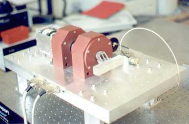
Figure 1: Magnetic bearing optical delay line
Introduction
The optical delay line initially developed by ULB during the EUCLID RTP 9.2 program and further improved by MICROMEGA DYNAMICS is based on the magnetic bearing technology. This optical delay line is to be integrated in an earth observation telescope using the Optical Aperture Synthesis technology. This requires stabilizing the optical path between the various telescopes and their common detector to some fraction of the light wavelength. The requirements of the optical delay line where mainly functional:
Sub-micrometric position devices are usually based on piezo-electric actuators. However, the stroke and bandwidth requirements disqualify them for this application. Indeed, although piezoelectric devices are able to achieve very high resolution (<1nm), their stroke is limited to 0.1% of their length. The only way to increase the stroke for a given actuator is to use complex amplification mechanisms (e.g. flexures). This reduces drastically the actuator stiffness and limits the achievable bandwidth. The use of two-stages systems (e.g. a piezo-electric actuator and ball bearings) can also increase the stroke, but the long stroke displacement has to be achieved very slowly (i.e. thermal effect).
Figure 1: Magnetic bearing optical delay line
For higher stroke/resolution ratios or for higher moving masses, the most adapted actuator is the voice-coil (or moving magnet) that allows a contact free force control over a long stroke. For these systems, the conception effort is aimed towards the guiding degrees-of-freedom (DOF), the main requirement being the lack of dry friction (stick-slip phenomenon). This can be achieved using flexure, air bearing and magnetic bearings. The main drawbacks of the flexures are the large ratio between the motion stroke and their size, in order to limit the fatigue problems, and the complexity of multiple DOF systems. The air bearings allow friction free displacements over large stroke but cannot be used in a space environment. On the other hand, despite their complexity, magnetic bearings provide a contact free guidance over long ranges. They can accommodate multiple DOF and they are compliant with void or space environment.
Breadboard
In order to demonstrate the effectiveness of magnetic bearings for high accuracy, long stroke devices, a breadboard based on commercially available components has been developed (Figure 1). The magnetic bearing (MECOS-T3336) provides guidance over 5 DOF while the piston movement is sensed by a laser interferometer (HP-5578A) and actuated by a voice-coil (ETEL-T2530). The control law is implemented in a DSP board (dSPACE DS-1102) and the GUI is implemented on MATLABTM. Both feedback and feedforward control laws have been implemented. Feedback provides stability, step responses and wide-band disturbance rejection. Feedforward can be used to cancel harmonic perturbations (if a correlated reference signal is available).
Performances
Axial Positioning
The stroke is 5mm, the positioning resolution is 12nmrms (over 100Hz) and the closed-loop bandwidth is 100Hz. The latter was mainly limited by the control structure interaction (CSI). Due to the saturation of the actuator, the settling time of the step response depends on the amplitude of the command (Figure 2). In the required configuration, the Optical Delay Line works in a perturbation rejection mode and the achieved sensitivity to perturbation is -60dB at 10Hz (Figure 3).
Figure 2: Step responses
Figure 3: Sensitivity to perturbations
Radial Guiding
The guiding system has an infinite static stiffness; it is only limited by the force produced by the magnets. The guiding error mainly depends on the sensor resolution (122nm quantification steps) and the bandwidth of the control system (1500Hz), the resulting guiding error is about 100nmrms (Figure 4). The four pairs of magnetic bearings dissipate a total of 3.5W. This comes either from the large bias current (1.5A), required to have the necessary control force, and the static control current that compensate the gravity. The use of permanent magnets to generate the bias magnetic flux can drastically reduces the first, while the second is not relevant for space application. Neglecting these static currents (i.e. horizontal bearings), the power dissipation can be estimated at 60mW (Figure 5).
Figure 4: Guidance error
Figure 5: Control current
Future improvements
The breadboard shown on Figure 1 is based on an off-the-shelf magnetic bearing system. This system was initially designed for high speed rotating machines. It was enough to demonstrate the concept but it is not really adequate for a high-stroke / high-resolution device:
Future works will tackle these points by: